6 Oracle CEP IDE for Eclipse and the Event Processing Network
This chapter describes how to use the Oracle Complex Event Processing (Oracle CEP) IDE for Eclipse to develop event processing networks (EPNs), where application components are wired together. The EPN Editor provides a graphical view of the EPN and offers visualization and navigation features to help you build Oracle CEP applications.
This section describes how to use the editor and the information it displays, including:
6.1 Opening the EPN Editor
You can open the EPN Editor from either the project folder or a context or configuration file of an Oracle CEP application.
6.1.1 How to Open the EPN Editor from a Project Folder
You can open the EPN Editor from the Eclipse project folder of an Oracle CEP application. Alternatively, you can open the EPN Editor from a context or configuration file (see Section 6.1.2, "How to Open the EPN Editor from a Context or Configuration File").
To open the EPN Editor from a project:
-
Launch the Oracle CEP IDE for Eclipse.
-
Open your Oracle CEP project in the Project Explorer.
-
Right-click the project folder and select Open EPN Editor as Figure 6-1 shows.
Figure 6-1 Opening the EPN Editor from a Project
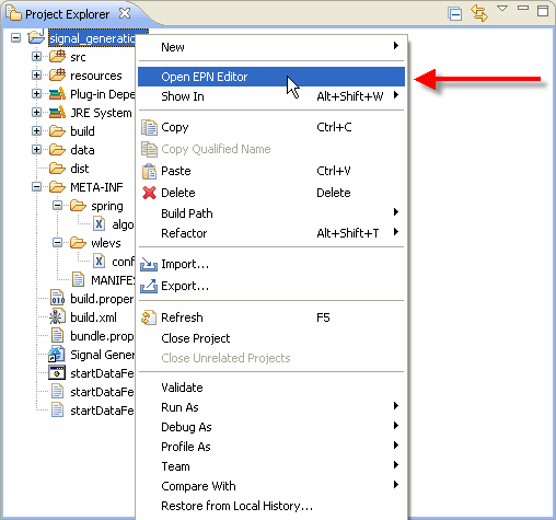
Description of "Figure 6-1 Opening the EPN Editor from a Project"
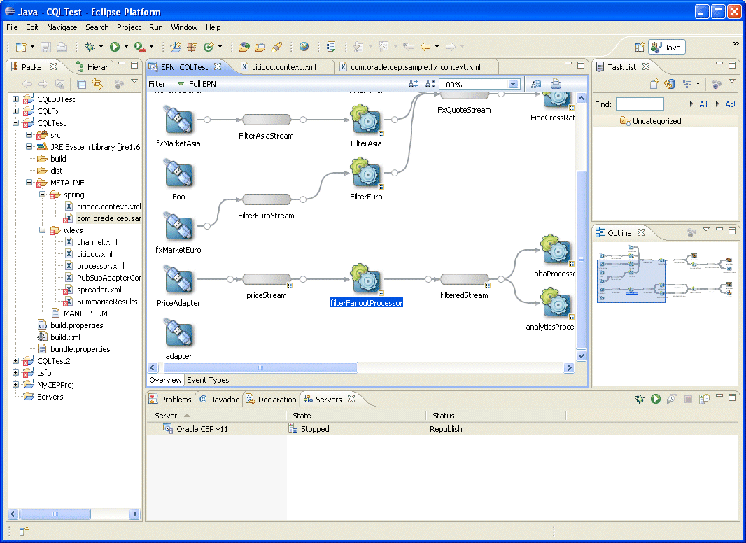
The EPN Editor opens in a tab named
EPN:PROJECT-NAME, wherePROJECT-NAMEis the name of your Oracle CEP project, as Figure 6-2 shows.
6.1.2 How to Open the EPN Editor from a Context or Configuration File
You can open the EPN Editor from a Spring context file or an Oracle CEP server configuration file in an Oracle CEP application. Alternatively, you can open the EPN Editor from a context or configuration file (see Section 6.1.1, "How to Open the EPN Editor from a Project Folder")
To open the EPN Editor from a context or configuration file:
-
Launch the Oracle CEP IDE for Eclipse.
-
Open your Oracle CEP project in the Project Explorer.
-
Right-click a context or configuration file and select Open in EPN Editor as Figure 6-3 shows.
Figure 6-3 Opening the EPN Editor from a Context or Configuration File
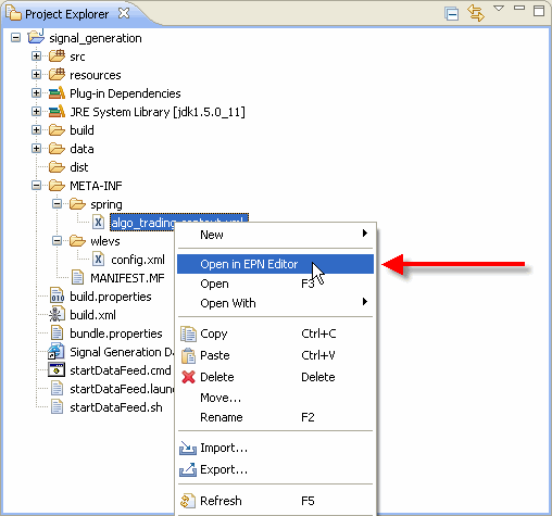
Description of "Figure 6-3 Opening the EPN Editor from a Context or Configuration File"
The EPN Editor opens in a tab named
EPN:PROJECT-NAME, wherePROJECT-NAMEis the name of your Oracle CEP project, as Figure 6-4 shows.
6.2 EPN Editor Overview
This section describes the main controls you use to manage the EPN view and how the EPN Editor displays Oracle CEP application information, including:
6.2.1 Flow Representation
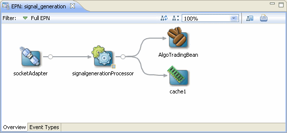
The primary display in the editor is of the flow inside the application as Figure 6-5 shows.
The EPN is composed of nodes connected by links and streams. Nodes are of various types including adapter, processor, database table, bean, and cache. For more information on the graphic notation the EPN Editor uses on nodes, links, and streams, see:
6.2.2 Filtering
Although you often specify your EPN in a single assembly file, you may specify an EPN across multiple assembly files.
By default the EPN Editor shows the EPN for a single Oracle CEP application bundle with the information combined from all files.
To see the network for a single assembly file simply select that file from the Filter pull-down menu as Figure 6-6 shows.
Figure 6-6 Filtering the EPN by Assembly File
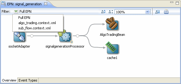
Description of "Figure 6-6 Filtering the EPN by Assembly File"
When editing an EPN, the assembly file shown in the EPN Editor filter is the assembly file to which new nodes will be added. If the EPN Editor filter is set to Full EPN then the first assembly file in the filter list will be the file to which new nodes will be added. Existing nodes will be edited in or deleted from the assembly file in which they are defined.
If the assembly file the EPN Editor edits is open in an Eclipse source editor, then the edits will be made to the editor for that open file. In this case, you will need to save changes to the open editor before the changes appear in the file on disk.
If the assembly file the EPN Editor edits is not open in an Eclipse source editor, then the edits are immediately applied to the file on disk.
For more information, see Section 4.3, "Creating EPN Assembly Files".
6.2.3 Zooming
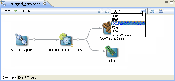
You can change the zoom level of the EPN Editor by entering a percent value into the zoom field or selecting a value from the zoom field pull-down menu as Figure 6-7 shows. To fit the EPN into the current EPN Editor window, select Fit to Window.
6.2.4 Layout
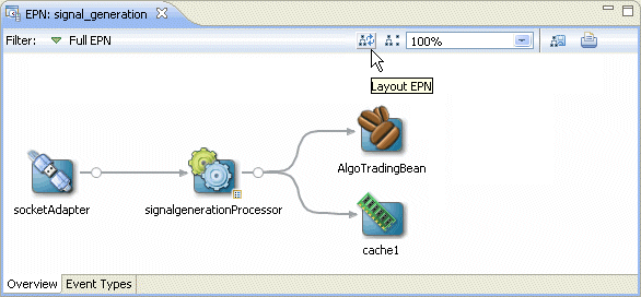
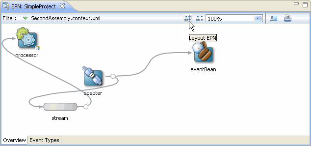
You can optimize and simplify the EPN layout by clicking Layout EPN as Figure 6-8 shows.
6.2.5 Showing and Hiding Unconnected Beans
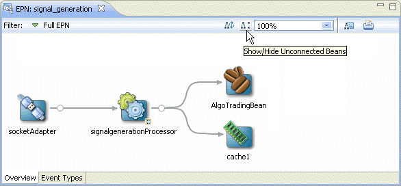
You can also filter out <bean> elements with no references in the EPN. Clicking Show/Hide Unconnected Beans will toggle the visibility of such beans as Figure 6-9 shows. For more information, see Section 6.4.3, "Laying Out Nodes".
6.2.6 Printing and Exporting to an Image
You can export the EPN Editor view to an image file by clicking Export to Image as Figure 6-10 shows. You can export the image as a .bmp, .gif, .jpg, or .png file.
Figure 6-10 Exporting the EPN as an Image File
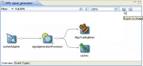
Description of "Figure 6-10 Exporting the EPN as an Image File"
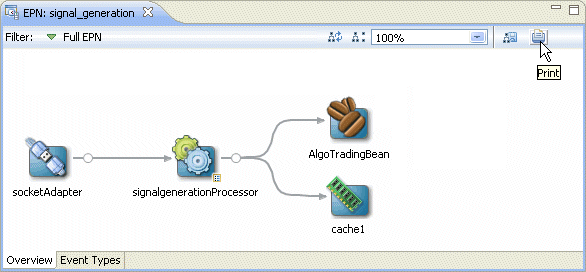
You can print the EPN Editor view by clicking Print as Figure 6-11 shows.
6.2.7 Configuration Badging
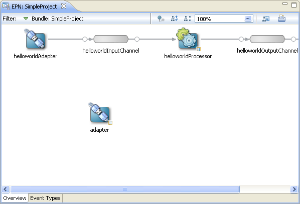
Nodes that have configuration information in one of the configuration files in the META-INF/wlevs directories are badged with an indicator on the bottom right as Figure 6-12 shows.
Nodes with this badge will also have the Go To Configuration Source context menu item.
6.2.8 Link Specification Location Indicator
When working with streams, you can specify a link in the assembly file as a:
-
source element in the downstream node.
-
listener element in the upstream node
A circle on the line indicates where a particular link is specified in the assembly file.
Figure 6-13 shows an example in which the link is specified as a source element on the downstream node outStream so the circle is next to the outStream node. Figure 6-14 shows the corresponding assembly file.
Figure 6-15 shows an example in which the link is specified as a listener element in the upstream node algoTradingProcessor so the circle is next to the algoTradingProcessor node. Figure 6-16 shows the corresponding assembly file.
6.2.9 Nested Stages
When you define a child node within a parent node, the child node is said to be nested. Only the parent node can specify the child node as a listener. You can drag references from a nested element, but not to them. For more information, see Section 6.4.2, "Connecting Nodes".
Consider the EPN that Figure 6-17 shows. Example 6-1 shows the EPN assembly source for this EPN. Note that the HelloWorldBean is nested within the helloworldOutputChannel. As a result, it appears within a box in the EPN diagram. Only the parent helloworldOutputChannel may specify the nested bean as a listener.
Example 6-1 Assembly Source for EPN With Nested Bean
<wlevs:adapter id="helloworldAdapter"
 class="com.bea.wlevs.adapter.example.helloworld.HelloWorldAdapter" >
    <wlevs:instance-property name="message" value="HelloWorld - the current time is:"/>
</wlevs:adapter>

<wlevs:channel id="helloworldInputChannel" event-type="HelloWorldEvent" >
    <wlevs:listener ref="helloworldProcessor"/>
    <wlevs:source ref="helloworldAdapter"/>
</wlevs:channel>

<wlevs:processor id="helloworldProcessor" />

<wlevs:channel id="helloworldOutputChannel" event-type="HelloWorldEvent" advertise="true">
    <wlevs:listener>
        <bean class="com.bea.wlevs.example.helloworld.HelloWorldBean"/>
    </wlevs:listener>
    <wlevs:source ref="helloworldProcessor"/>
</wlevs:channel>
Alternatively, you can define this EPN so that all nodes are nested as Figure 6-18 shows. Example 6-2 shows the EPN assembly source for this EPN. Note that all the nodes are nested and as a result, all nodes appear within a box in the EPN diagram. The helloworldAdapter is the outermost parent node and does not appear within a box in the EPN diagram.
Example 6-2 Assembly Source for EPN With all Nodes Nested
<wlevs:adapter id="helloworldAdapter" class="com.bea.wlevs.adapter.example.helloworld.HelloWorldAdapter" >
    <wlevs:instance-property name="message" value="HelloWorld - the current time is:"/>
    <wlevs:listener>
        <wlevs:channel id="helloworldInputChannel" event-type="HelloWorldEvent" >
            <wlevs:listener>
                <wlevs:processor id="helloworldProcessor">
                    <wlevs:listener>
                        <wlevs:channel id="helloworldOutputChannel" event-type="HelloWorldEvent">
                            <wlevs:listener>
                                <bean class="com.bea.wlevs.example.helloworld.HelloWorldBean"/>
                            </wlevs:listener>
                        </wlevs:channel>
                    </wlevs:listener>
                </wlevs:processor>
            </wlevs:listener>
        </wlevs:channel>
    </wlevs:listener>
</wlevs:adapter>
6.2.10 Event Type Repository Editor
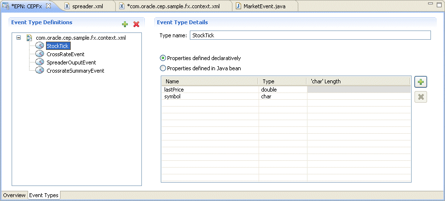
You can create and edit JavaBean and tuple event types using the event type repository editor.
To open the event type repository editor, click on the Event Types tab in the EPN editor as Figure 6-19 shows.
For more information, see:
For information on the other types of events you can create, see Section 1.1.2, "Oracle CEP Event Types".
6.3 Navigating the EPN Editor
Because the EPN Editor has a view of the whole project it is a natural place from which to navigate to the various artifacts that make up an Oracle CEP application. Oracle CEP IDE for Eclipse offers the following features to help navigate the EPN Editor:
6.3.1 Moving the Canvas
To move the EPN canvas without using the horizontal and vertical scroll bars, you can use any of the following options:
-
Position the cursor on the canvas, hold down the middle mouse button, and drag.
-
Hold down the space bar and click and drag the canvas.
-
In the Overview view, click in the highlight box and drag.
6.3.2 Shortcuts to Component Configuration and EPN Assembly Files
If a node has a configuration object associated with it, then double-clicking that node will open the component configuration file where that node's behavior is defined.
Otherwise, double-clicking that node will open the EPN assembly file (the Spring context file) where that node is defined.
A configuration badge will be shown on nodes with associated configuration objects as shown in Figure 6-20.
Figure 6-20 Node with Configuration Badge

Description of "Figure 6-20 Node with Configuration Badge"
For more information, see:
6.3.3 Hyperlinking
When editing a component configuration file, EPN assembly file, or Oracle CQL statement, hold down the Ctrl key to turn on hyperlinking. Using hyperlinking, you can easily move between assembly and configuration files and follow reference IDs to jump to bean implementation classes.
This section describes:
6.3.3.1 Hyperlinking in Component Configuration and EPN Assembly Files
Figure 6-21 shows a component configuration file with the cursor over the value of a processor element name child element while holding down the Ctrl key. The name value has an underline to indicate it is a hyperlink. Click this link to jump to the corresponding element in the EPN assembly file as Figure 6-22 shows.
Figure 6-21 Component Configuration File: Hyperlinking to EPN Assembly File
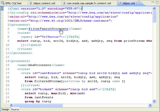
Description of "Figure 6-21 Component Configuration File: Hyperlinking to EPN Assembly File"
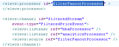
Similarly, hovering over the wlevs:processor element id child element value filterFanoutProcessor while holding down the Ctrl key allows you to hyperlink back to the component configuration file.
Figure 6-22 EPN Assembly File: Hyperlinking to Component Configuration File
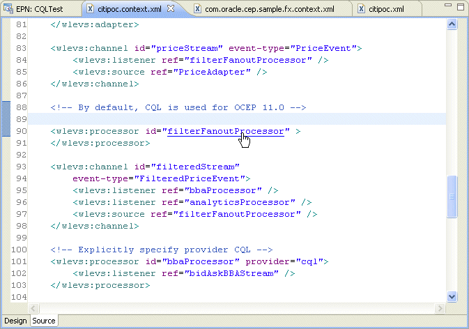
Description of "Figure 6-22 EPN Assembly File: Hyperlinking to Component Configuration File "
6.3.3.2 Hyperlinking in Oracle CQL Statements
Figure 6-23 shows a component configuration file with the cursor over an event attribute while holding down the Ctrl key. The fromRate attribute has an underline to indicate it is a hyperlink. Click this link to jump to the corresponding event definition in the EPN assembly file as Figure 6-24 shows.
Note:
Hyperlinking in Oracle SQL statements is designed for simple use cases and may not work as expected in more complex implementations.
Figure 6-23 Oracle CQL Statement: Event Schema
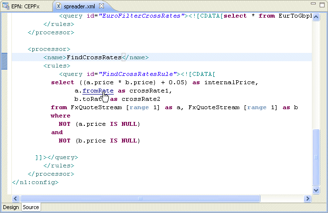
Description of "Figure 6-23 Oracle CQL Statement: Event Schema"
Figure 6-24 Corresponding Event Definition in EPN Assembly File
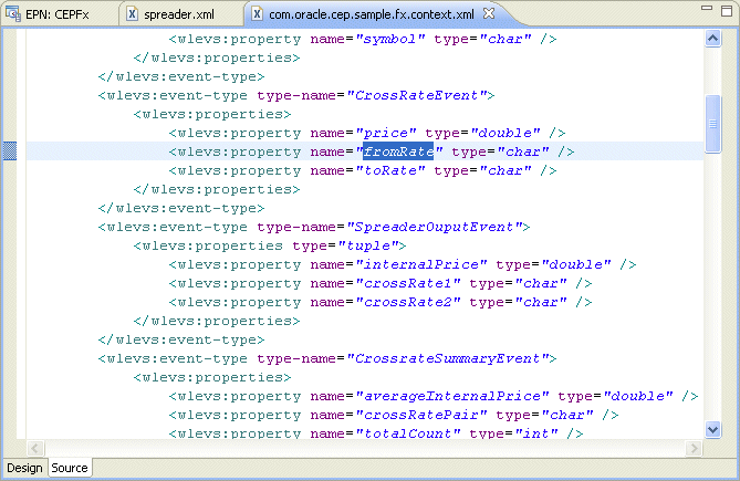
Description of "Figure 6-24 Corresponding Event Definition in EPN Assembly File"
Similarly, you can Ctrl-click the FxQuoteStream channel in the Oracle CQL statement that Figure 6-23 shows to jump to the channel's definition. This is applicable wherever references to external objects are present in a Oracle CQL statement.
6.3.4 Context Menus
Each node on the EPN Editor has a group of context menu items that provide convenient access to various node-specific functions. Right-click the node to display its context menu.
Depending on the node type, you can use the EPN Editor context menu to select from the following options:
-
Go to Configuration Source: opens the corresponding component configuration file and positions the cursor in the appropriate element. You can use hyperlinking to quickly move from this file to the corresponding EPN assembly file. For more information, see Section 6.3.3, "Hyperlinking".
-
Go to Assembly Source: opens the corresponding EPN assembly file and positions the cursor in the appropriate element. You can use hyperlinking to quickly move from this file to the corresponding component configuration file. For more information, see Section 6.3.3, "Hyperlinking"
-
Go to Java Source: opens the corresponding Java source file for this component.
-
Delete: deletes the component from both the EPN assembly file and component configuration file (if applicable).
-
Rename: allows you to change the name of the component. The name is updated in both the EPN assembly file and component configuration file (if applicable).
-
Help: displays context sensitive help for the component.
Note that these navigation options will become disabled when a corresponding source artifact cannot be found. For example, if an adapter does not have a corresponding entry in a configuration XML file, its Go to Configuration Source menu item will be greyed out.
6.3.5 Browsing Oracle CEP Types
A typical Oracle CEP project contains many instances of Oracle CEP types such as adapters, channels, processors, event beans. In a large, complex Oracle CEP project, it can be a challenge to locate a particular instance. The Oracle CEP IDE for Eclipse provides an Oracle CEP type browser that you can use to quickly locate instances of any Oracle CEP type.
6.3.5.1 How to Browse Oracle CEP Types
You can open the Oracle CEP type browser using the keyboard short cut Ctrl-Alt-T.
-
Open an Oracle CEP project.
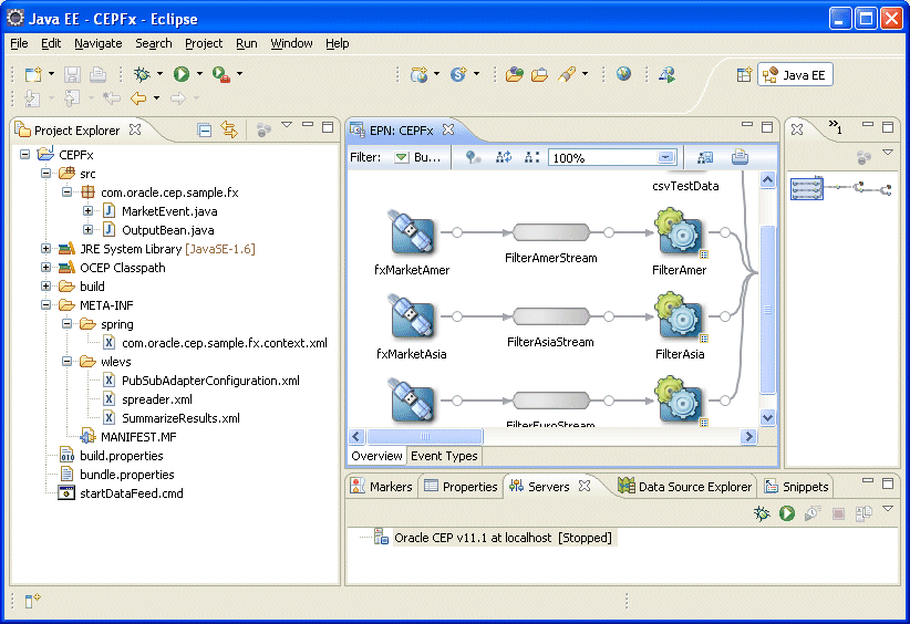
In the following procedure, consider the Oracle CEP project that Figure 6-25 shows. This is based on the Oracle CEP foreign exchange example. For more information on this example, see "Foreign Exchange (FX) Example" in the Oracle Fusion Middleware Getting Started Guide for Oracle Complex Event Processing.
-
Type the keyboard short cut Ctrl-Alt-T.
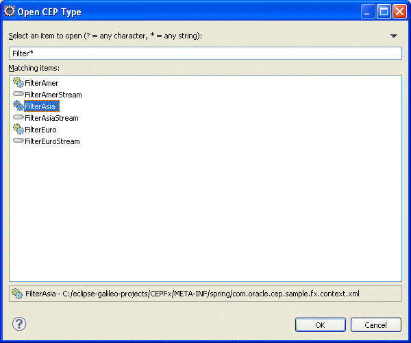
The Oracle CEP type browser appears as Figure 6-26 shows.
-
Configure the Oracle CEP Type dialog as shown in Table 6-1.
Table 6-1 Oracle CEP Type Dialog
Attribute Description Select an item to open
Specify a filter to match the names of the items you wan to find.
Use the
?wildcard for any single character and the*wildcard for any string of two or more characters.Matching items
The list of Oracle CEP type instances whose name matches the filter you specified.
By default, the status line below the Matching items list shows the fully qualified path to the selected item in the Select an item to open list. To toggle status line display, click on the pull-down menu in the right hand corner and select Show Status Line.
-
Select a type in the Matching Items list and click OK.
The type is opened in the source file in which it is defined. For example, selecting
FilterAsiafrom the Matching Items list and clicking OK opens thecom.oracle.cep.sample.fx.content.xmlEPN assembly file in which this processor is defined as Figure 6-27 shows.Figure 6-27 Opening the FilterAsia EPN Assembly File
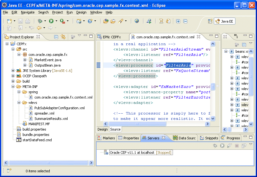
Description of "Figure 6-27 Opening the FilterAsia EPN Assembly File"
To navigate to the corresponding component configuration file as Figure 6-28 shows, Ctrl-click the FilterAsia
idattribute value.Figure 6-28 Opening the FilterAsia Component Configuration File
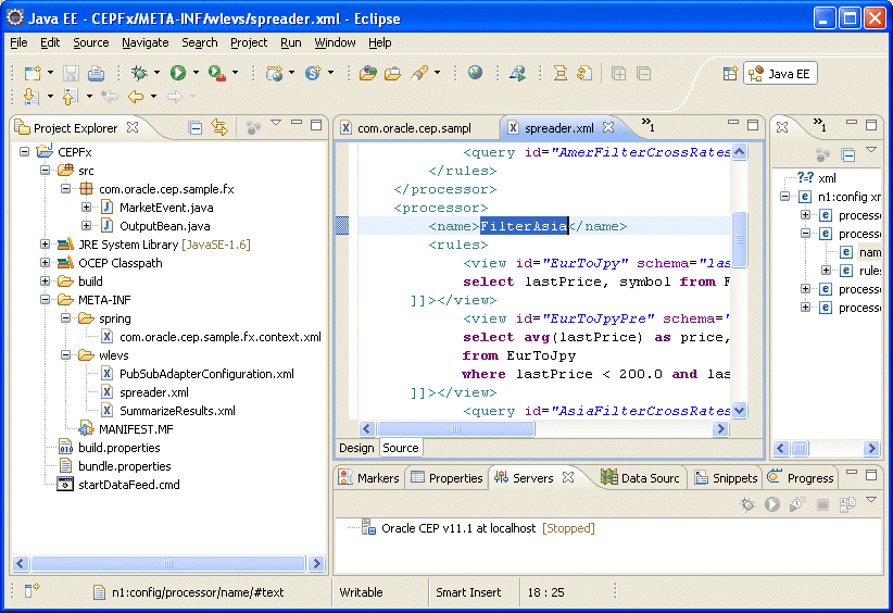
Description of "Figure 6-28 Opening the FilterAsia Component Configuration File"
For more information on hyperlinking, see Section 6.3.3, "Hyperlinking".
6.4 Using the EPN Editor
The EPN Editor allows you to create and edit an application's EPN using actions on the editor surface. Most actions in the EPN Editor result in edits to an assembly file in that application. You can use a single EPN assembly file or multiple EPN assembly files (for more information, see Section 6.2.2, "Filtering").
The following sections describe EPN Editor editing tasks, including:
For more information, see:
6.4.1 Creating Nodes
When adding new nodes to an EPN using the EPN editor, a new node will appear at the location of the mouse click that was used to show the EPN Editor context menu. You can create any of the nodes that Table 6-2 lists.
The user may not reposition the nodes on the EPN Editor. To refresh the layout of the nodes on the EPN Editor, click the Layout EPN button on the EPN Editor toolbar. For more information, see Section 6.4.3, "Laying Out Nodes".
When a child node is nested within a parent node, its icon appears within a box. For more information, see Section 6.2.9, "Nested Stages".
6.4.1.1 How to Create a Basic Node
Basic nodes include beans, caches, channels, event beans, and tables.
For information on how to create other nodes, see Section 6.4.1, "Creating Nodes".
-
Open the EPN Editor (see Section 6.1, "Opening the EPN Editor").
-
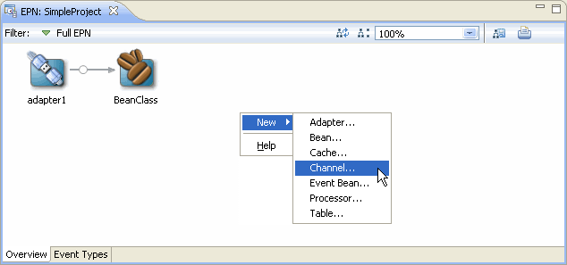
Right-click on an empty portion of the EPN Editor surface and select New from the context menu as Figure 6-29 shows.
-
Select the type of node you want to create.
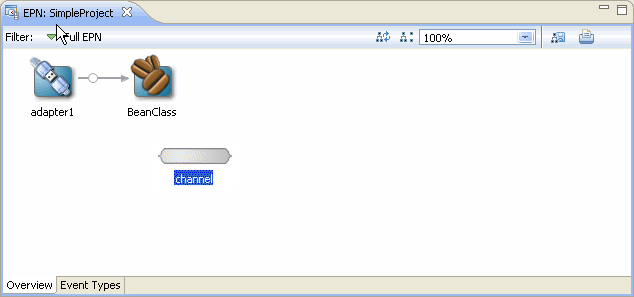
The EPN Editor edits the source file indicated in the EPN Editor filter and the EPN Editor displays the new EPN node. For most nodes, a default ID is chosen and the new node is immediately opened for rename as Figure 6-30 shows.
To rename the node, see Section 6.4.4, "Renaming Nodes".
To reposition the node and update the EPN Editor layout, see Section 6.4.3, "Laying Out Nodes".
-
Optionally, configure additional node options.
See:
6.4.1.2 How to Create an Adapter Node
This section describes how to create an adapter using the EPN Editor, including:
-
JMS adapters (in-bound or out-bound)
-
HTTP publish-subscribe server adapters (publishing or subscribing)
For information on how to create other nodes, see Section 6.4.1, "Creating Nodes".
-
Open the EPN Editor (see Section 6.1, "Opening the EPN Editor").
-
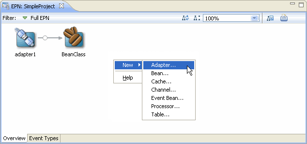
Right-click on an empty portion of the EPN Editor surface and select New from the context menu as Figure 6-31 shows.
-
Select node type Adapter.
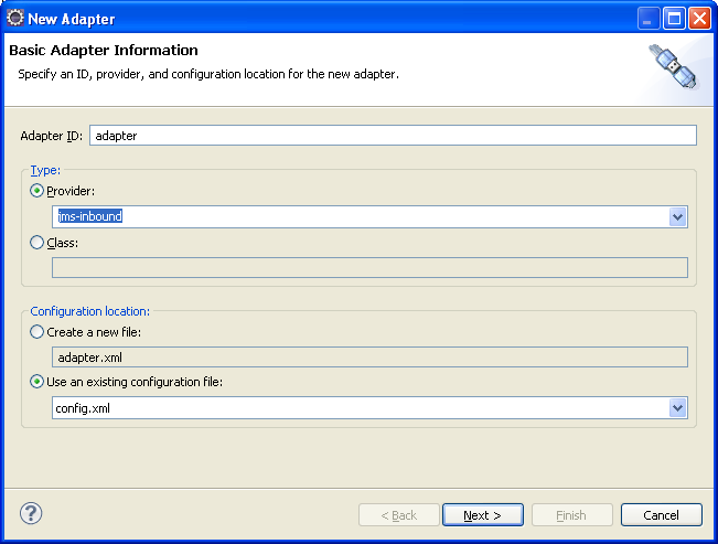
The New Adapter wizard appears as shown in Figure 6-32.
-
Configure the New Adapter Wizard - Page 1 as shown in Table 6-3.
Table 6-3 New Adapter Wizard - Page 1
Attribute Description Adapter ID
Specifies the ID of the adapter EPN element and the name of the associated adapter configuration element.
Provider
Select the adapter provider type from the pull-down menu for an adapter already defined in the Oracle CEP component configuration schema.
Select one of:
-
jms-inbound: JMS in-bound adapter.
-
jms-outbound: JMS out-bound adapter.
-
httppub: HTTP publish-subscribe adapter for publishing.
-
httpsub: HTTP publish-subscribe adapter for subscribing.
Class
Specify the fully qualified Java class name of a custom adapter.
NOTE: If you are using a custom adapter factory, you must add the
wlevs:factoryelement manually. For more information, see Chapter 14, "Configuring Custom Adapters".Create a new file
Creates the adapter component configuration in a new file.
The new file is created in the application's
META-INF/wlevsdirectory with the same name as the adapter ID.Use an existing configuration file
Creates the adapter component configuration in an existing configuration file.
The new adapter configuration element is appended to the configurations in the selected file.
-
-
Proceed depending on how you configured the adapter implementation:
-
The provider-specific New Adapter Wizard page appears.
-
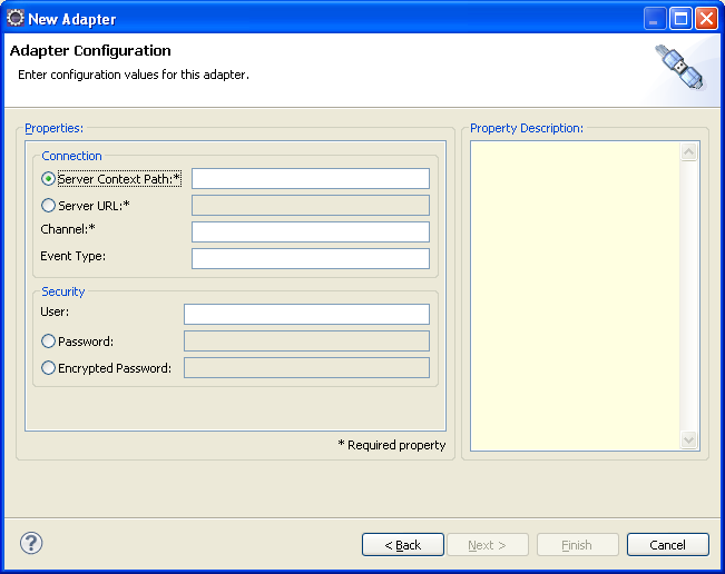
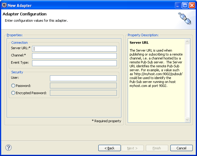
Configure the provider-specific New Adapter Wizard page as the following figures show:
-
Figure 6-33, "New Adapter Wizard - jms-inbound"
See Section 7.6.1, "JMS Inbound Adapter Component Configuration".
-
Figure 6-34, "New Adapter Wizard - jms-outbound"
See Section 7.6.2, "JMS Outbound Adapter Component Configuration".
-
Figure 6-35, "New Adapter Wizard - httppub"
See Section 8.5.1, "HTTP Pub-Sub Adapter for Publishing Component Configuration".
-
Figure 6-36, "New Adapter Wizard - httpsub"
See Section 8.5.2, "HTTP Pub-Sub Adapter for Subscribing Component Configuration".
Figure 6-33 New Adapter Wizard - jms-inbound
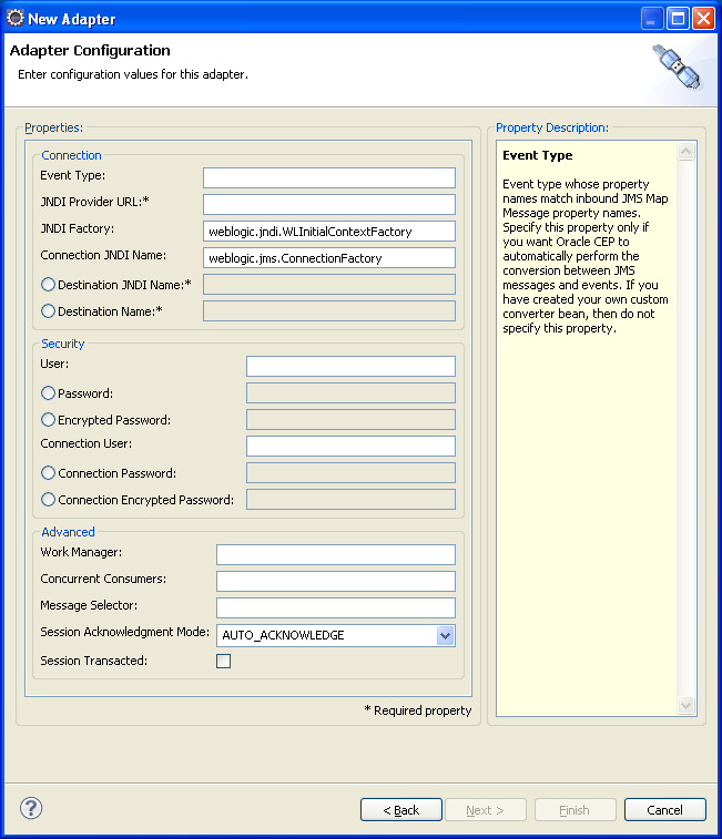
Description of "Figure 6-33 New Adapter Wizard - jms-inbound"
Figure 6-34 New Adapter Wizard - jms-outbound
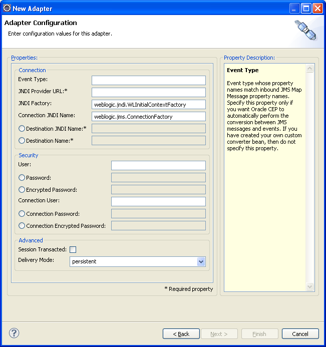
Description of "Figure 6-34 New Adapter Wizard - jms-outbound"
-
-
Use the new adapter node on the EPN.
The EPN Editor creates the adapter configuration in the file you specified in the New Adapter wizard, edits the source file indicated in the EPN Editor filter, and displays the new EPN node as Figure 6-37 shows.
To rename the node, see Section 6.4.4, "Renaming Nodes".
To reposition the node and update the EPN Editor layout, see Section 6.4.3, "Laying Out Nodes".
-
Optionally, configure additional node options.
For more information, see:
6.4.1.3 How to Create a Processor Node
This section describes how to create a processor node using the EPN Editor. For information on creating other node types, see Section 6.4.1.1, "How to Create a Basic Node".
When deploying an Oracle CEP application with a wlevs:processor node, other nodes in an EPN may reference that processor only if a processor configuration exists for that processor. Processor configurations are defined in Oracle CEP application configuration files. See Section 1.1.5, "Component Configuration Files" for more information about CEP configuration files.
-
Open the EPN Editor (see Section 6.1, "Opening the EPN Editor").
-
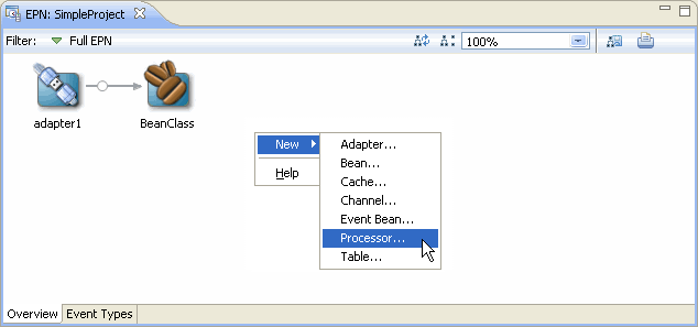
Right-click on an empty portion of the EPN Editor surface and select New from the context menu as Figure 6-38 shows.
-
Select node type Processor.
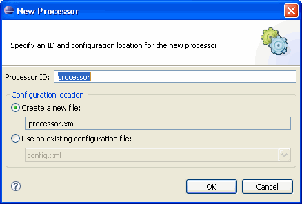
The New Processor dialog appears as shown in Figure 6-39.
-
Configure the New Processor dialog as shown in Table 6-4.
Table 6-4 New Processor Dialog
Attribute Description Processor ID
Specifies the ID of the processor EPN element and the name of the associated processor configuration element
Create a new file
Creates the processor configuration in a new file.
The new file is created in the application's
META-INF/wlevsdirectory with the same name as the processor ID.Use an existing configuration file
Creates the processor configuration in an existing configuration file.
The new processor configuration element is appended to the configurations in the selected file.
-
Click OK.
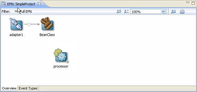
The EPN Editor creates the processor configuration in the file you specified in the New Processor dialog, edits the source file indicated in the EPN Editor filter, and displays the new EPN node as Figure 6-40 shows.
To rename the node, see Section 6.4.4, "Renaming Nodes".
To reposition the node and update the EPN Editor layout, see Section 6.4.3, "Laying Out Nodes".
Note:
In Oracle CEP, you must use a channel to connect a push event source to an Oracle CQL processor and to connect an Oracle CQL processor to an event sink. For more information, see Section 9.1.2, "Channels Representing Streams and Relations".
-
Optionally, configure additional processor options.
See:
6.4.2 Connecting Nodes
The nodes in the EPN represent the flow of events through an Event Processing Network of an Oracle CEP application. When a node may forward events to another node in the EPN, the EPN Editor allows you to connect that node visually by dragging a line from the source node to the destination node.
6.4.2.1 How to Connect Nodes
This section describes how to connect nodes in the EPN Editor.
-
Open the EPN Editor (see Section 6.1, "Opening the EPN Editor").
-
Select the source of events and drag to the target of the event flow.
-
If a connection is allowed, a plug icon is shown at the target end as Figure 6-41 shows.
Figure 6-41 Connecting Nodes: Connection Allowed
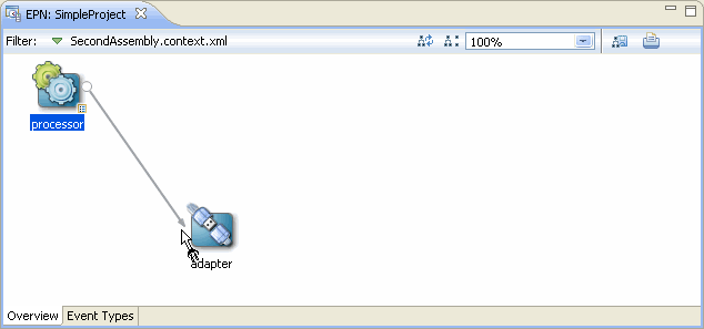
Description of "Figure 6-41 Connecting Nodes: Connection Allowed"
-
If the connection is not allowed, a forbidden icon is shown at the target end as Figure 6-42 shows.
Figure 6-42 Connecting Nodes: Connection Forbidden
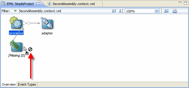
Description of "Figure 6-42 Connecting Nodes: Connection Forbidden"
Not all nodes may be a target of event flow. For example, connection is forbidden if:
-
A node does not define a valid identifier.
-
A node is nested (for more information, see Section 6.2.9, "Nested Stages").
-
-
-
Release the mouse button to complete the connection.
When the connection is made, the EPN Editor updates the EPN assembly file. For example:
-
When you connect an adapter to a channel or a channel to a processor or event bean, the EPN Editor adds a
wlevs:listenerelement to the source node with a reference to the target node by ID. -
When you connect a table to a processor, the EPN Editor adds a
wlevs:table-sourceelement to the target processor node that references the source table.
For example, suppose you connect the adapter to the channel, and the channel to the processor shown in Figure 6-43.
Figure 6-44 shows the EPN assembly file before connection.
Figure 6-44 EPN Assembly File: Before Connection
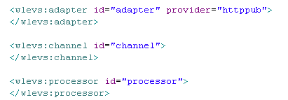
Description of "Figure 6-44 EPN Assembly File: Before Connection"
Figure 6-45 shows the EPN assembly file after connection.
Figure 6-45 EPN Assembly File: After Connection
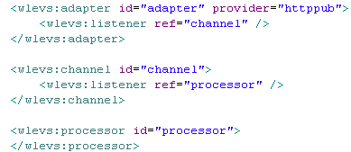
Description of "Figure 6-45 EPN Assembly File: After Connection"
-
6.4.3 Laying Out Nodes
Certain EPN Editor actions will use the location of the action as the location of the rendered result. For example, when adding new nodes to an EPN using the EPN editor, a new node will appear at the location of the mouse click that was used to show the EPN Editor context menu. The user may not reposition the nodes on the EPN Editor. To refresh the layout of the nodes on the EPN Editor, click the Layout EPN button on the EPN Editor toolbar as Figure 6-46 shows.
For more information, see Section 6.2.4, "Layout".
6.4.4 Renaming Nodes
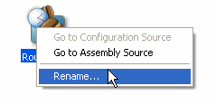
Most node types support a rename operation that will change all references to the node across both assembly and configuration XML files. You can select Rename from the node's context menu as Figure 6-47 shows.
6.4.5 Deleting Nodes
You may delete most nodes and connections visible on the EPN Editor using the node's context menu or the Delete key:
-
Using the keyboard, select the object you want to delete and then click the Delete key.
-
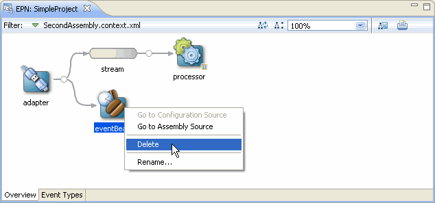
Using the context menu, right-click on the object to show the context menu, then select Delete as Figure 6-48 shows.
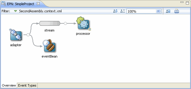
When deleting a node, the incoming and outgoing connections are also deleted. For example, Figure 6-49 shows the EPN and Figure 6-51 shows the assembly file before deleting the channel node named stream.
Figure 6-49 EPN Before Deleting a Channel Node
Description of "Figure 6-49 EPN Before Deleting a Channel Node"
Figure 6-50 Assembly File Before Deleting a Channel Node

Description of "Figure 6-50 Assembly File Before Deleting a Channel Node"
Figure 6-51 shows the EPN and Figure 6-52 shows the assembly file after deleting this channel node.
Figure 6-51 EPN After Deleting a Channel Node
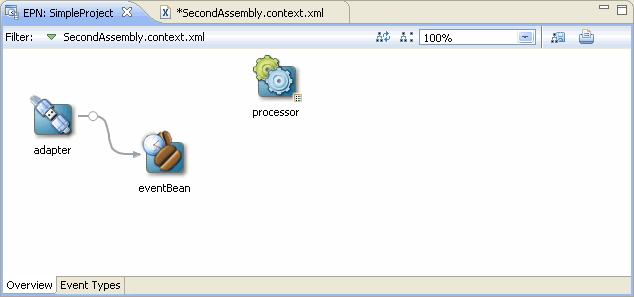
Description of "Figure 6-51 EPN After Deleting a Channel Node"
Figure 6-52 Assembly File After Deleting a Channel Node
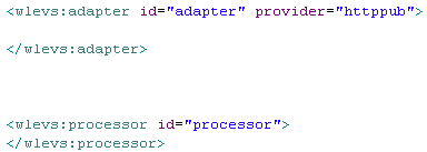
Description of "Figure 6-52 Assembly File After Deleting a Channel Node"
Note:
If a bean or other anonymous element is deleted, then the object containing that object is deleted too. For example, given a bean within a wlevs:listener element, then deleting the bean will delete the listener element too.
