| Skip Navigation Links | |
| Exit Print View | |

|
Oracle Solaris Administration: Network Interfaces and Network Virtualization Oracle Solaris 11 Information Library |
| Skip Navigation Links | |
| Exit Print View | |

|
Oracle Solaris Administration: Network Interfaces and Network Virtualization Oracle Solaris 11 Information Library |
1. Overview of the Networking Stack
Network Configuration in This Oracle Solaris Release
The Network Stack in Oracle Solaris
Network Devices and Datalink Names
Administration of Other Link Types
3. NWAM Configuration and Administration (Overview)
4. NWAM Profile Configuration (Tasks)
5. NWAM Profile Administration (Tasks)
6. About the NWAM Graphical User Interface
Part II Datalink and Interface Configuration
7. Using Datalink and Interface Configuration Commands on Profiles
8. Datalink Configuration and Administration
9. Configuring an IP Interface
10. Configuring Wireless Interface Communications on Oracle Solaris
12. Administering Link Aggregations
16. Exchanging Network Connectivity Information With LLDP
Part III Network Virtualization and Resource Management
17. Introducing Network Virtualization and Resource Control (Overview)
18. Planning for Network Virtualization and Resource Control
Network Virtualization and Resource Control Task Map
Planning and Designing a Virtual Network
Basic Virtual Network on a Single System
Best Uses for the Basic Virtual Network
Private Virtual Network on a Single System
Implementing Controls on Network Resources
Interface-based Resource Control for a Traditional Network
Best Use of Interface-based Resource Control on a Traditional Network
Flow Control for the Virtual Network
How to Create a Usage Policy for Applications on a Virtual Network
How to Create a Service Level Agreement for the Virtual Network
19. Configuring Virtual Networks (Tasks)
20. Using Link Protection in Virtualized Environments
21. Managing Network Resources
This section describes two different scenarios for configuring a virtual network. Look over the scenarios to help determine which most closely fits the needs of your site. Then use that scenario as the basis for designing your specific virtualization solution. The scenarios include:
Basic virtual network of two zones, especially useful for consolidating network services from the local network onto a single host.
Private virtual network, useful for a development environment where you isolate applications and services from the public network.
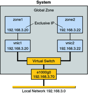
Figure 18-1 shows the basic virtual network, or “network in a box” that is used in examples throughout the section Configuring Components of Network Virtualization in Oracle Solaris.
Figure 18-1 Virtual Network on a Single Host

This virtual network consists of the following:
A single GLDv3 network interface e1000g0. This interface connects to the public network 192.168.3.0/24. Interface e1000g0 has the IP address 192.168.3.70.
A virtual switch, which is automatically configured when you create the first VNIC.
Two VNICs. vnic1 has the IP address 192.168.3.20, and vnic2 has the IP address 192.168.3.22.
Two exclusive IP zones to which the VNICs are assigned. vnic1 is assigned to zone1, and vnic2 is assigned to zone2.
The VNICs and zones in this configuration allow access to the public. Therefore, the zones can pass traffic beyond the e1000g0 interface. Likewise, users on external networks can reach applications and services offered by the zones.
The network in a box scenario enables you to isolate processes and applications into individual virtual machines or zones on a single host. Furthermore, this scenario is expandable to include many containers, each of which could run a completely isolated set of applications. The scenario improves a system's efficiency and, by extension, the efficiency of the local network. Therefore, this scenario is ideal for the following users:
Network consolidators and others who want to consolidate the services of a LAN onto a single system.
Any site that rents out services to customers. You can rent out individual zones or virtual machines, observe traffic, and take statistics for performance measuring or for billing purposes on each zone in the virtual network.
Any administrator who wants to isolate processes and applications to separate containers to improve system efficiency .
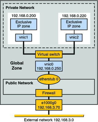
Figure 18-2 shows a single system with a private network behind packet filtering software that performs network address translation (NAT). This figure illustrates the scenario that is built in Example 19-5.
Figure 18-2 Private Virtual Network on a Single Host

The topology features a single system with a public network, including a firewall, and a private network built on an etherstub pseudo-interface. The public network runs in the global zone and consists of the following elements:
GLDv3 network interface e1000g0 with the IP address 192.168.3.70.
A firewall implemented in the IP Filter software. For an introduction to IP Filter, refer to Introduction to IP Filter in Oracle Solaris Administration: IP Services.
etherstub0, a pseudo-interface upon which the virtual network topology is built. Etherstubs provide the ability to create a virtual network on a host. That network is totally isolated from the external network.
The private network consists of the following elements:
A virtual switch which provides packet forwarding among the VNICs of the private network.
vnic0, which is the VNIC for the global zone, and has the IP address 192.168.0.250.
vnic1 with the IP address 192.168.0.200 and vnic2 with the IP address 192.168.0.220. All three VNICs are configured over etherstub0.
vnic1 is assigned to zone1, and vnic2 is assigned to zone2.
Consider creating a private virtual network for a host that is used in a development environment. By using the etherstub framework, you can totally isolate software or features under development to the containers of the private network. Moreover, you can use firewall software for network address translation of outgoing packets that originate from the containers of the private network. The private network is a smaller version of the eventual deployment environment.
For procedures that configure a virtual network and implement the scenarios described in this chapter, go to Creating a Private Virtual Network.
For conceptual information about VNICs and virtual networks, go to Network Virtualization and Virtual Networks.
For conceptual information about zones, go to Chapter 15, Introduction to Oracle Solaris Zones, in Oracle Solaris Administration: Oracle Solaris Zones, Oracle Solaris 10 Zones, and Resource Management.
For information about IP Filter, go to Introduction to IP Filter in Oracle Solaris Administration: IP Services.